Finding the current registration
Before I did any serious work on the project, it was clear that I would have to find a way of detecting which stops were drawn at any one time, to process the data for that instant. The first thing therefore, was to multiplex the stop information, so it could be understood by the rest of the system.

The first components laid out on bread-board.
There's a guiding hard-copy of the rudimentary stages of a schematic in evidence here (without any "input conditioning" shown).
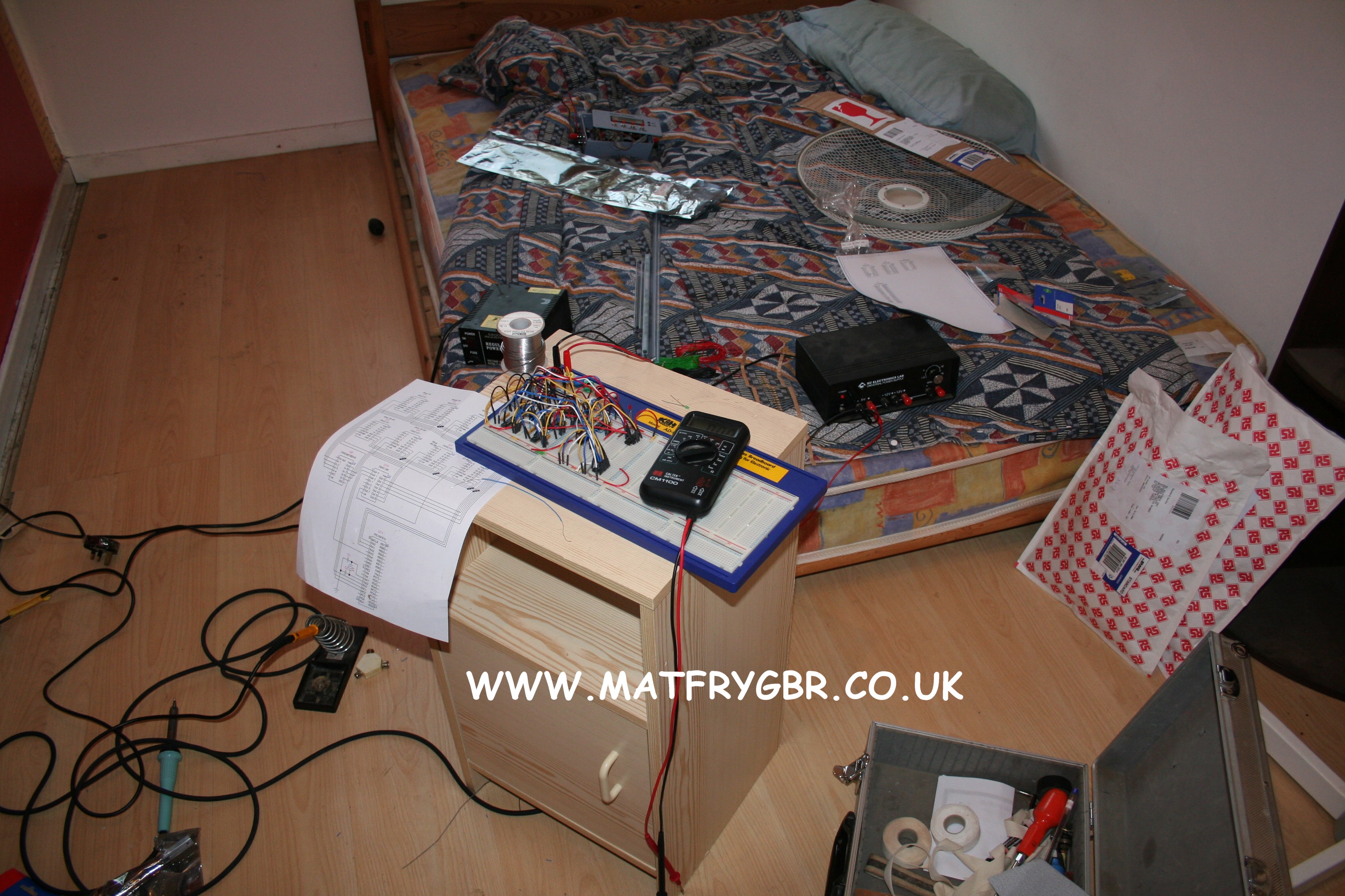
Another angle. Note the power supply used here. It was given to me as a gift from Bogaziçi University, Istanbul, when I worked over there a few years ago!
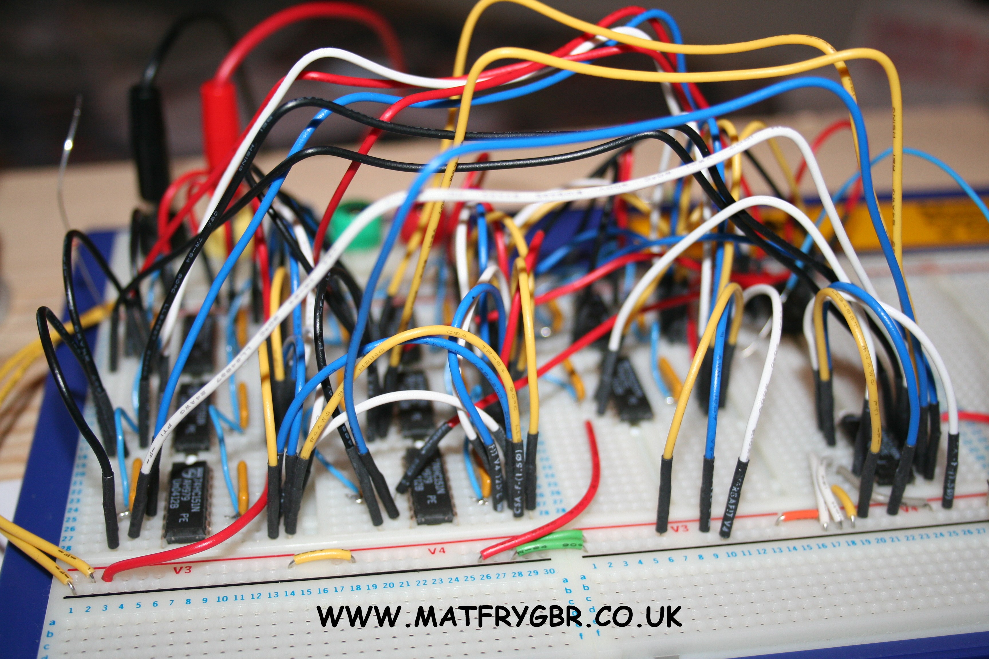
A close-up of some the interconnecting "rats nest" wiring.
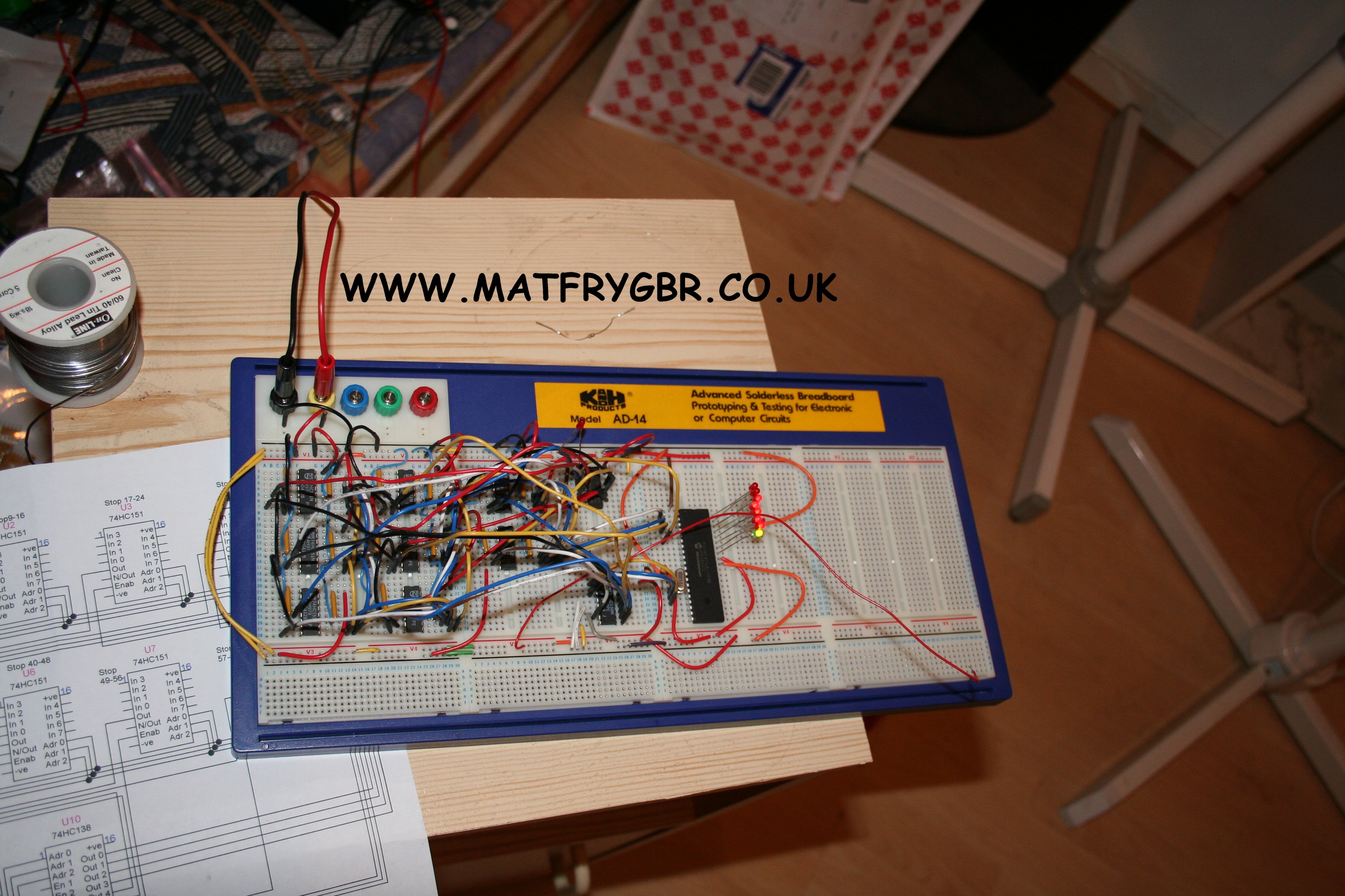
One step on from the previous shot. First CPU appearance, plus a really basic system to display current address lines. For any geeks reading this, the Least Significant Bit (LSB) is denoted by its LED being green. The maximum that can be displayed using the eight LED's, is 255 if they were all on. Here, the LED's are telling me that the 64th input was the last one touched with my test lead (2 to the power of 6).
Note the absence of series resistors for the LED's. These have their own built-in resistors. Makes life so much easier.
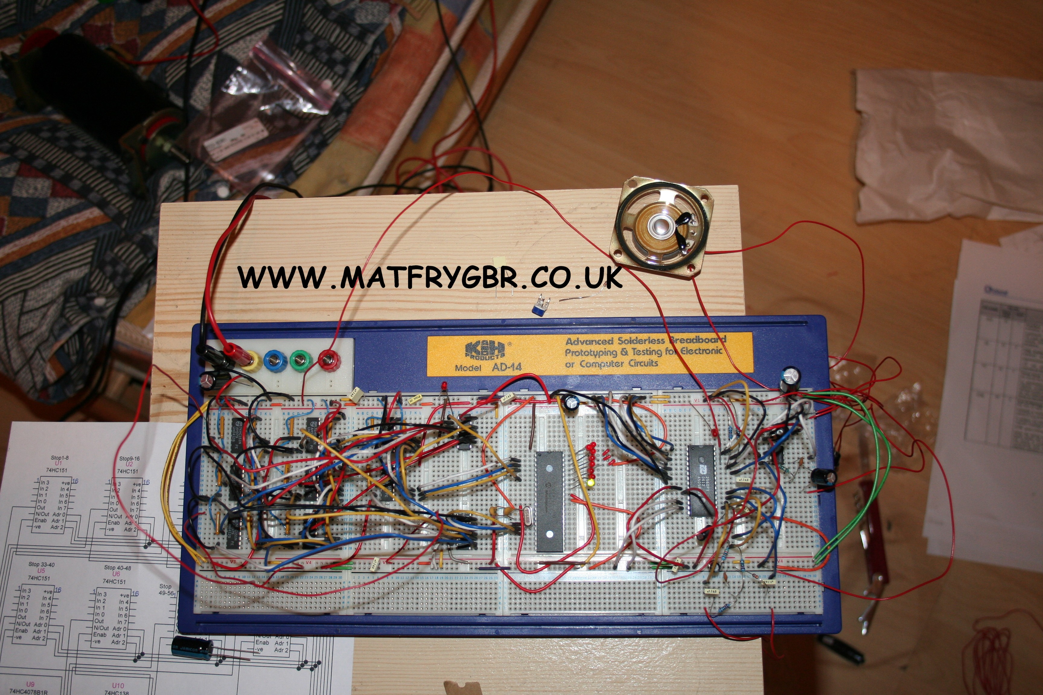
The right side of the bread-board here, has a separate function to the left. On the right, the first speech device I tried is being auditioned. Although it showed a bit of promise, it never made it any further, as I discovered a more complex, more fitting device, with loads more capacity!
The left side is telling me that the first input (no. 1) has been touched with my test lead!
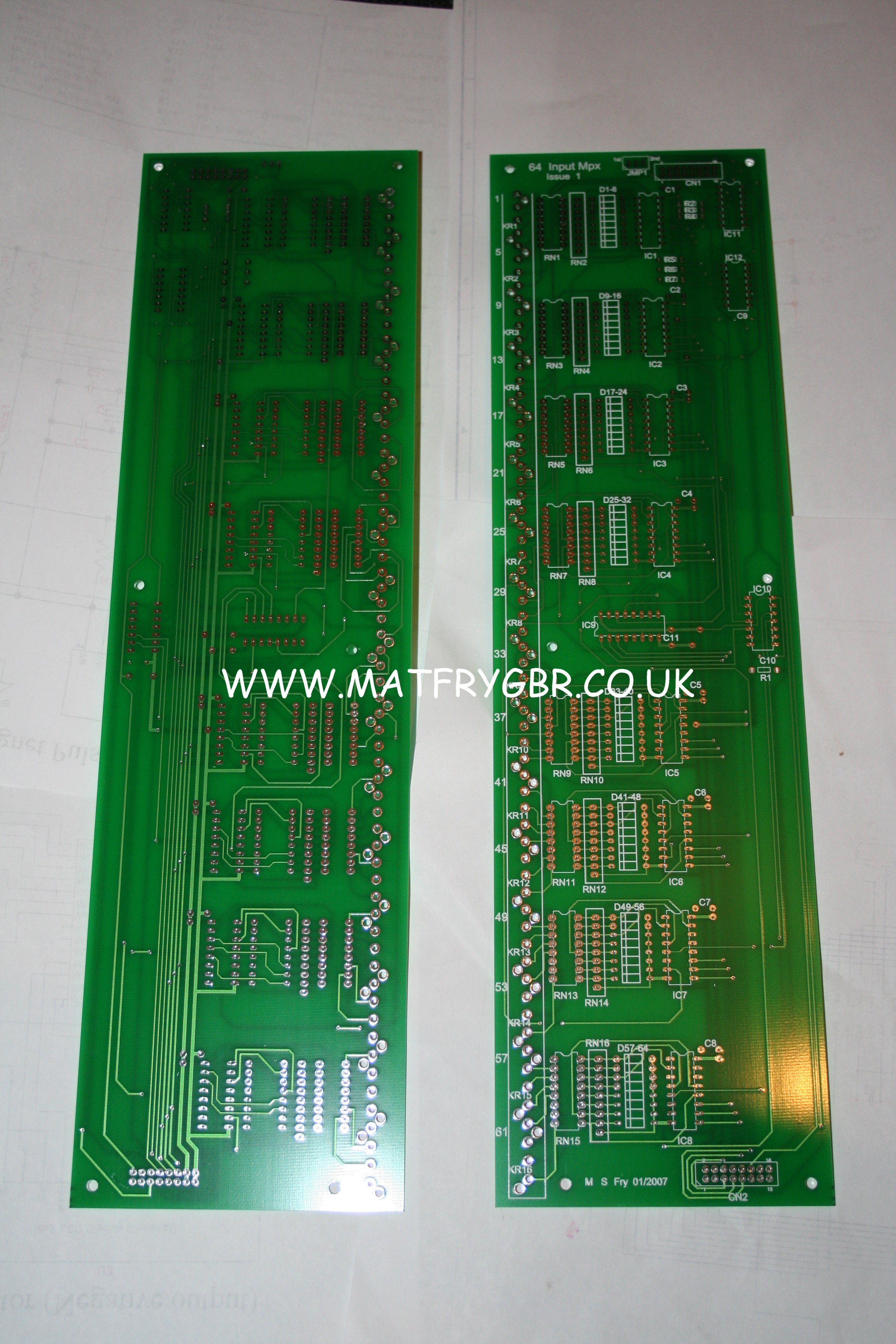
After quite some time of translating the results I got from my prototyping with the bread-board model, I came up with a design for a PCB to put it on.
I used a company in China for the PCB production, as it was the cheapest option. After sending the Gerber file details to them, with my initial payment, I had to wait for an agonizing three or so weeks until I received the finished boards.
Gerber files are the protocol for PCB information. They contain the various layers. This includes the track layout, the drill centres, the silk-screen info (the legend on the PCB) and solder-mask details (the area of lacquer, normally green, that solder will not melt onto).
These are my first professionally produced PCB's, and I was pleasantly surprised with the result.
Both sides can be seen here.
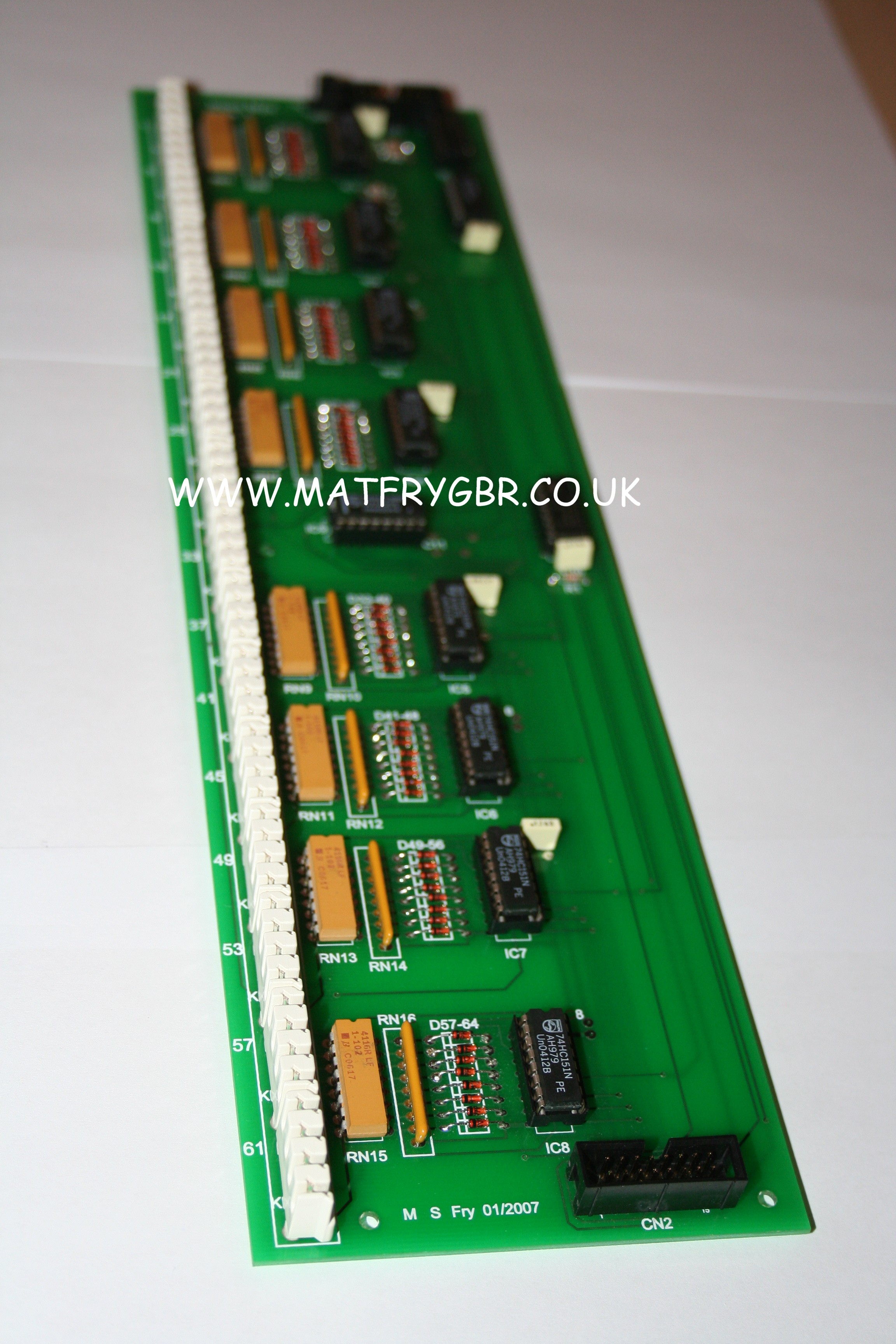
The fully populated input board. The first part of the project is complete.
There now follows a pretty intensive development phase, getting the most out of a Microchip PIC device!
The more eagle-eyed among you will notice that the prototypes here are being clocked at a very pedestrian 4 MHz! The system as it stands now, is running at 20 MHz - still not blazing (well within the processors limit), but hopefully pretty safe.